|
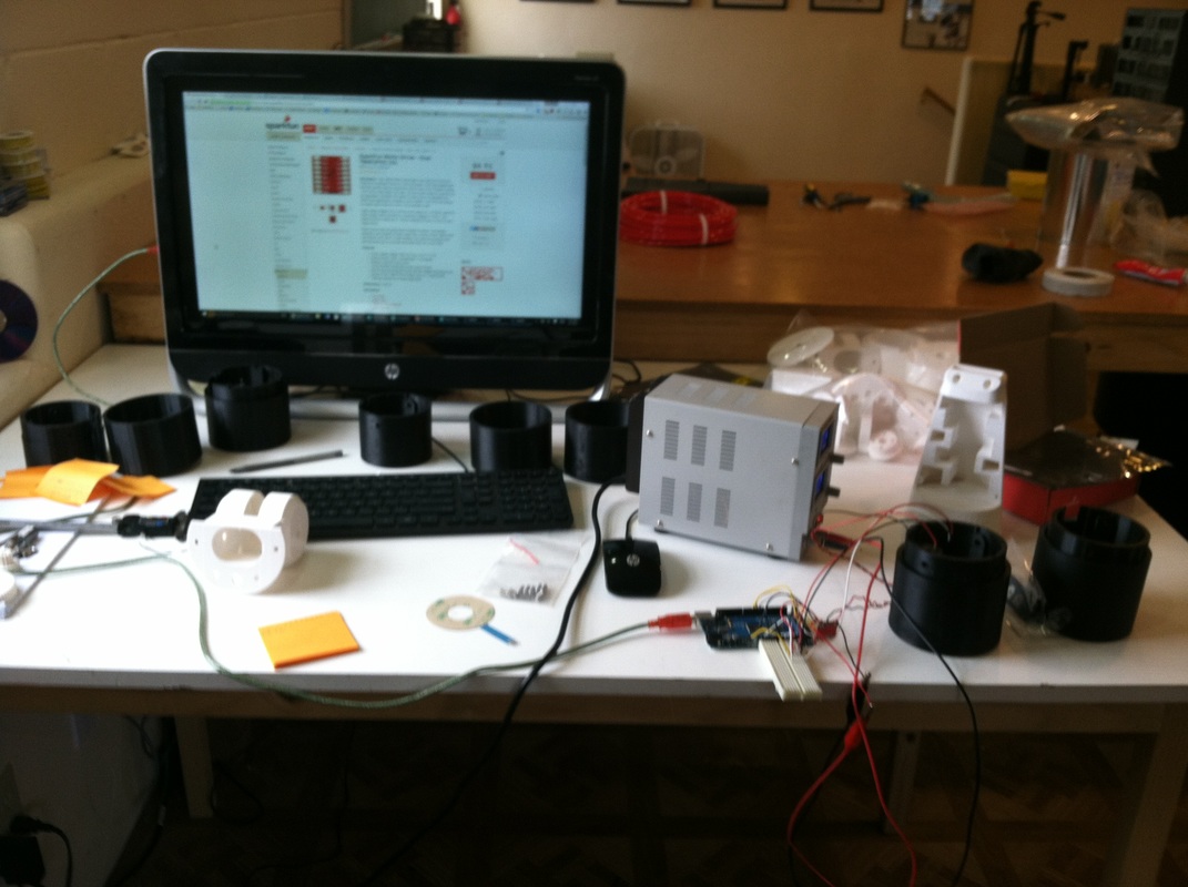
During my LINK internship, I was tasked with creating a project that I could show during the final exhibition. For my project, I created the rotation joint for the robotic arm. The purpose of this part is to simulate a human arm and hand rotating. In order to achieve this, I designed two chambers. One chamber holds a motor with a shaft running through the bottom. At the end of this shaft is a small spur gear. The second chamber is larger with an internal spur gear running along its interior. The motor chamber can be placed inside the gear chamber, allowing the gear attached to the motor to run along the internal spur gear. If energy is transmitted to the motor, its chamber will rotate around and simulate arm rotation. I
|
also added hall effect sensory to the rotation joint. Hall effect sensors are able to detect and record the amplitude of magnetic polarity. Very close and powerful positive polarity will transmit a high value, while negative polarity will transmit a low value. I placed two magnets will opposing polarity on either side of the gear chamber, and placed a hall effect sensor in the motor chamber. Therefore, the hall effect sensor can record how close it is to either magnet and therefore know its rotary position. With this information, I was able to write code to program the rotation joint to move. If I wanted the rotation joint to move a certain distance, I could simply tell it to rotate in a specific direction until the hall effect sensor reached a certain value. For example, if I wanted the rotation joint to rotate 90 degrees, I could simply tell it to rotate until the hall effect sensor lined up with the positive magnet, giving a sensor value of 384. With the rotation joint completed, the robotic arm can now simulate arm rotation.
